Author Topic: 12v Regulated power supply  (Read 2742 times)

12v Regulated power supply
« on: 06 October, 2015, 05:36:41 pm »
I'm replacing the 12v 20W halogen light fittings in my cooker extractor hood (which in contrast to the build quality of the rest had a poxy plastic surround which, after 10 years has gone). I've found suitably shaped 3W LED units, which are specified to be driven from 12v DC. The transformer output is 13.4vAC so it is up to 19v if I full wave convert it.

I'm assuming I'm going to have to convert to DC, otherwise the flickering is going to be too distracting.

I'm trying to decide whether to use a zener or a voltage regulator, I'm going to make one for each side so each only has to provide about 250mw, I thought I would design in for 500mw. Found some circuits for both online, but suggestions welcome.

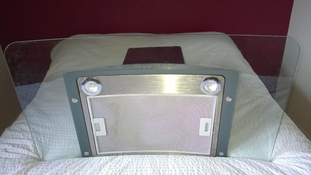
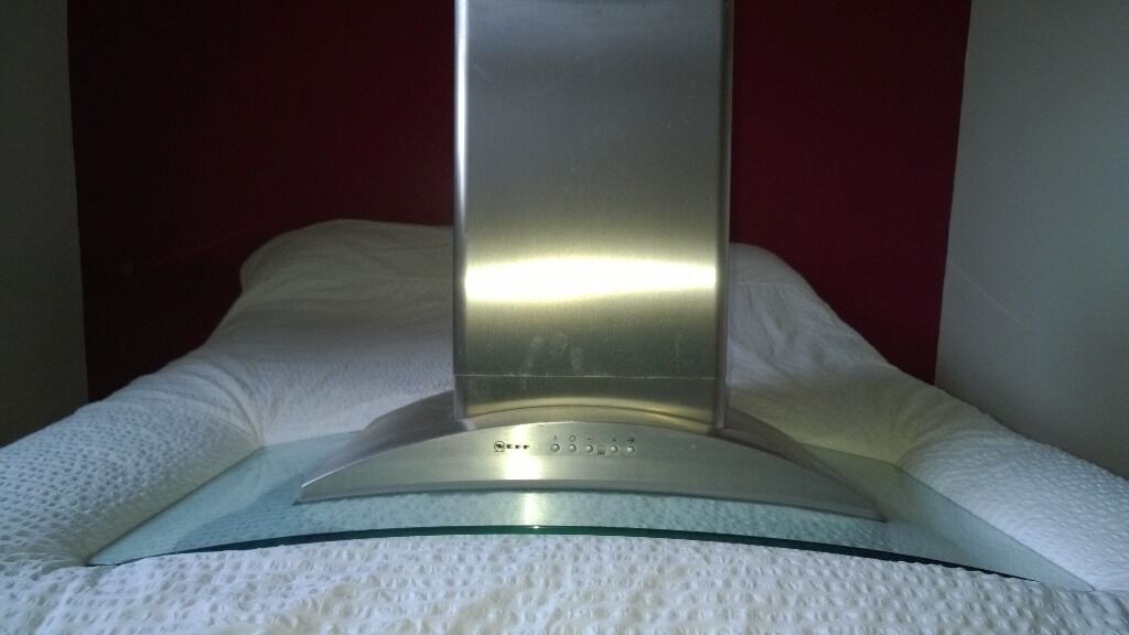
The hood is this one, so any wires from one side to the other will have to cross the middle section, where there are likely mains voltages, hence the two converters. There's enough room in the boxwork for components, but it will be enclosed so no heat dispersion.


And the lights can be seen in this

frankly frankie

  • I kid you not
    • Fuchsiaphile
Re: 12v Regulated power supply
« Reply #1 on: 06 October, 2015, 05:43:33 pm »
I'm assuming I'm going to have to convert to DC, otherwise the flickering is going to be too distracting.

You could wire them in antiphase.
when you're dead you're done, so let the good times roll

Kim

  • Timelord
    • Fediverse
Re: 12v Regulated power supply
« Reply #2 on: 06 October, 2015, 06:07:18 pm »
What I'd do is wire the fittings in series and supply them from a 250mW constant-current source that'll give the ~24V required.  A couple of SONs in series ought to do it  ;), or you could maybe get a constant current module designed for driving LED lighting... (LEDs prefer being driven by constant-current sources, so these things are readily available off-the-shelf.)

If the topography is really that annoying you could use a driver for each fitting.

Kim

  • Timelord
    • Fediverse
Re: 12v Regulated power supply
« Reply #3 on: 06 October, 2015, 06:11:00 pm »
I'm assuming I'm going to have to convert to DC, otherwise the flickering is going to be too distracting.

You could wire them in antiphase.

That'll halve the frequency and make the flicker even more irritating!

TBH, I wouldn't drive LED lighting at less than 400Hz or so, and only then if you want to PWM dim it.

Re: 12v Regulated power supply
« Reply #4 on: 06 October, 2015, 06:27:24 pm »
Anything off the shelf is likely not to fit in the space, anything component related probably will.

If I wire in series, won't the notional voltage requirement go up to 24v? I'm limited to the switched (probably soft-switched relay, at a guess transformer based as there's no reson for anything else) 13v AC

I've had a poke around for circuits and I'm now thoroughly confused.

Kim

  • Timelord
    • Fediverse
Re: 12v Regulated power supply
« Reply #5 on: 06 October, 2015, 06:39:43 pm »
Anything off the shelf is likely not to fit in the space, anything component related probably will.

Ah, right.

You can get rather nifty little modules that do the constant-current thing when fed DC, which would probably be happy with with your rectified/smoothed transformer output.  I recently used a Meanwell LDD series driver for my desk lamp LED retrofit.


Quote
If I wire in series, won't the notional voltage requirement go up to 24v? I'm limited to the switched (probably soft-switched relay, at a guess transformer based as there's no reson for anything else) 13v AC

My mistake - I was assuming you could retire the transformer and get at the mains.

Kim

  • Timelord
    • Fediverse
Re: 12v Regulated power supply
« Reply #6 on: 06 October, 2015, 06:45:05 pm »
Unfortunately the LDD-L series only goes down to 300mA.  Otherwise that would seem ideal.

Re: 12v Regulated power supply
« Reply #7 on: 06 October, 2015, 07:11:23 pm »
I had these in the halogen fitting http://www.ultraleds.co.uk/g4-24-led-cool-white-ip67-waterproof-12v-ac-dc-180-lumen.html

There must be a component hidden in the board, the only SM components I can see are apparently 4 little black things (diodes?) 4 x 1B00 (capacitor?) 2 x 22R0 (resistor?) and that worked fine ;)

Seems a shame I can't replicate that......

Kim

  • Timelord
    • Fediverse
Re: 12v Regulated power supply
« Reply #8 on: 06 October, 2015, 07:36:30 pm »
I had these in the halogen fitting http://www.ultraleds.co.uk/g4-24-led-cool-white-ip67-waterproof-12v-ac-dc-180-lumen.html

There must be a component hidden in the board, the only SM components I can see are apparently 4 little black things (diodes?) 4 x 1B00 (capacitor?) 2 x 22R0 (resistor?) and that worked fine ;)

The clue's in the 1 year warranty...

Re: 12v Regulated power supply
« Reply #9 on: 06 October, 2015, 09:23:35 pm »
I used a buckpuck for a bike light. It was pretty reliable and a constant current source, took a huge voltage range.

How much space do you have? I have several transformers left over from lights bought to go on the boat.
Just checked, there is an ikea one for LEDs in the shed. Half palm-sized
<i>Marmite slave</i>

Re: 12v Regulated power supply
« Reply #10 on: 06 October, 2015, 10:16:03 pm »
Referring to the photo (not of mine, but the same model) the central area has the control board. That's likely to have the transformer on board along with the control logic circuitry.  Getting into that area is more of a pain than I would want to as it will involve removal from the wall and major strip down with massive scope for stuff to go wrong. The selfsame lights are available, but they are priced at £55 a pop which provides the motivation to sort it.

The area with the lights is the internal hollow section formed by the sheet metal, and has plenty of space to stuff things into. But, the only connections exposed are the 13v AC leads, so thanks for the offer but more transformers wouldn't help.

Re: 12v Regulated power supply
« Reply #11 on: 06 October, 2015, 10:43:15 pm »
Found this that looks likely:

http://www.instructables.com/id/Power-LED-s---simplest-light-with-constant-current/

With R3 set to c1.6 ohm for 300ma (such as or if I want to go 1W for both)

If I'm reading it right the mosfeft can handle the voltage and current https://www.fairchildsemi.com/datasheets/FQ/FQP50N06L.pdf

I'd add full wave rectification and a capacitor across the v out  (electrolytic? 1000uf?) and it might even work ? ? ?

Re: 12v Regulated power supply
« Reply #12 on: 08 October, 2015, 09:27:42 pm »
Parts are on order for the constant current circuit... but shirley I ought to drop the voltage, too?


Kim

  • Timelord
    • Fediverse
Re: 12v Regulated power supply
« Reply #13 on: 08 October, 2015, 10:01:12 pm »
Parts are on order for the constant current circuit... but shirley I ought to drop the voltage, too?

The nature of a constant current source is that (within the limits of its ability to regulate imposed by the design) the voltage changes to whatever is required to maintain that current in the load.

We're used to thinking in terms of voltage sources, which supply (again within limits) the current required in order to maintain a given voltage across a load.  Batteries and mains power both behave more-or-less like constant[1]-voltage sources, which is why we're familiar with them.  Current sources are relatively rare in the physical world (bicycle dynamos are a good approximation), but obviously you can design an electronic power regulator to regulate either.

Short answer:  The regulator sets the current, your LED determines the voltage.


[1] The mains for AC values of constant.

Feanor

  • It's mostly downhill from here.
Re: 12v Regulated power supply
« Reply #14 on: 08 October, 2015, 10:16:15 pm »
I've read this thread a couple of times, and I'm not sure about this.
Has this been completely thought through?
Are you trying to drive raw LEDs, or LEDs with a built-in PSU?

You say the 3W LED units you have require 12vDC.
That sounds like they already contain the current source PSU circuit, and are expecting a 12v ( ish ) regular constant voltage supply.

The circuit you show ( the current supply ) is for powering raw LEDs, not LEDs with an incorporated PSU.
Although it might just work, as to get the current up as required, your current supply might need to ramp up the voltage to 12v ( rather than the 3 * 0.7v or whatever required for the raw LEDs ).

If the fittings have a built-in constant current PSU ( which I suspect they do ), then they may be tolerant of a range of input voltages.
If full-wave rectification of the 12vAC is a wee bit hot, then perhaps half-wave rectification, and a wee capacitor might be within the voltage range.


Re: 12v Regulated power supply
« Reply #15 on: 08 October, 2015, 11:05:44 pm »
Which is, kind of, where I started. Half wave rectification seems a bit too much like a cop out, and likely to result in flicker unless I use a BFO capacitor, it is drawing 250mA after all. I've tried connecting a 12V DC LED to  AC (not this one) and it wasn't pretty (but it is half wave rectified, of course)

The fitting just says "12V DC" (with polarity). Clearly summat is going on, but I iz hignorant as to what without digging into the innards of my nice noo shiny.

Providing a regulated 12v supply seemed fairly straightforward, in the first place.....

Biggsy

  • A bodge too far
  • Twit @iceblinker
    • My stuff on eBay
Re: 12v Regulated power supply
« Reply #16 on: 09 October, 2015, 12:09:20 pm »
Anything off the shelf is likely not to fit in the space

Not necessarily if you discard the case.
●●●  My eBay items  ●●●  Twitter  ●●●

Re: 12v Regulated power supply
« Reply #17 on: 09 October, 2015, 05:34:15 pm »
OK.

So. I've applied 12v from a switched supply, and it seems to light ok. The supply in the hood is going to be a transformer in all likelihood (you can hear a 50hz hum) so is going to be better still. Full wave rectification, voltage regulation seems like the best way to go.

If it works, what can go wrong?

Feanor

  • It's mostly downhill from here.
Re: 12v Regulated power supply
« Reply #18 on: 09 October, 2015, 11:46:00 pm »
Full-wave rectify, a cap, and a 7812 1-Amp reg is about as simple as a PSU gets.

If it's drawing about 500mA ( based on 2x3W at 12v: 6/12=0.5 ),
and the regulator has to drop say 19v to 12v so lets say 7v @ 0.5A, it's going to be dissipating about 3.5W.
I think that's going to get a bit hot, so I'd think a switching regulator would be more appropriate than a linear regulator.

Or just feed the things over-voltage DC and see how they get on?
They contain a current mode PSU, and may well be quite tolerant of some input overvoltage.
Is there an actual spec, beyond the 'nominal' input voltage?

Or a cheap ebay 12v in-line encapsulated PSU with 240 in one end and 12v out the other?
They are pretty much matchbox sized.

I'm not offering to buy replacements if you blow them up!


Biggsy

  • A bodge too far
  • Twit @iceblinker
    • My stuff on eBay
Re: 12v Regulated power supply
« Reply #19 on: 10 October, 2015, 11:19:24 am »
But avoid the very cheapest Chinese PSUs off eBay if you like to be safe.

See www.youtube.com/user/bigclivedotcom/videos for Big Clive's videos on cheap PSUs and LED lights.
●●●  My eBay items  ●●●  Twitter  ●●●

Re: 12v Regulated power supply
« Reply #20 on: 10 October, 2015, 01:39:10 pm »
Why don't you just buy a couple of 240 volt LEDs?

http://www.ledfix.co.uk/led-fire-rated-downlights.html

Re: 12v Regulated power supply
« Reply #21 on: 10 October, 2015, 02:14:52 pm »
Full-wave rectify, a cap, and a 7812 1-Amp reg is about as simple as a PSU gets.

That's pretty much what I'm thinking of doing

Quote
If it's drawing about 500mA ( based on 2x3W at 12v: 6/12=0.5 ),
and the regulator has to drop say 19v to 12v so lets say 7v @ 0.5A, it's going to be dissipating about 3.5W.
I think that's going to get a bit hot, so I'd think a switching regulator would be more appropriate than a linear regulator.
I'm going to build one for each side, so more like 0.25A and 1.75W dissipation, it is inside a closed area, but I was going to bolt it to a small heatsink and give it a whirl. The chip has thermal protection, and even if it went up in flames there's little flamm..... oops. Cooker hood? Fat deposits? complete with forced ventilation and flue? Hmmmm


Quote
Or just feed the things over-voltage DC and see how they get on?

I'm actually beginning to think simpler.
What about just lobbing in a 28 ohm resistor, like this - at 5W there's a good bit of headroom. If my calculation is right a 22 should give me 13.5v

Quote


They contain a current mode PSU, and may well be quite tolerant of some input overvoltage.
Is there an actual spec, beyond the 'nominal' input voltage?


Nope. And it was quite clear that the "technical" guy knew less than me, so no ide what's inside the (rivited) box and at 10 a pop I'm not going to experiment

Quote
Or a cheap ebay 12v in-line encapsulated PSU with 240 in one end and 12v out the other?
They are pretty much matchbox sized.

I'm not offering to buy replacements if you blow them up!

As above, problem is I can't get to the 240

David Martin

  • Thats Dr Oi You thankyouverymuch
Re: 12v Regulated power supply
« Reply #22 on: 10 October, 2015, 06:09:36 pm »
If you just let it sit on AC it will flash at 50Hz. The reverse voltage isn't going to blow the LEDs, is it?


"By creating we think. By living we learn" - Patrick Geddes

Re: 12v Regulated power supply
« Reply #23 on: 10 October, 2015, 06:11:16 pm »
No, not on AC, the flashing would be crap. Rectify to DC, 1000uf 25 capacitor, 22ohm resistor in series.

At least that's the current thinking.

IGMC

Re: 12v Regulated power supply
« Reply #24 on: 12 October, 2015, 08:12:42 am »
Egil soon provokes the wrath of Arinbjorn and Gunnhilda......ooops, wrong saga.

Well, kept on thinking that it was strange for something so well engineered that I would have to disassemble to get to the components, and so it proves. I took off the cowl to paint the ceiling and took the opportunity to delve a little deeper.

What I thought was a spot weld encasing the electronic gubbins in was a spot weld holding in the base chassis, an admirable but cunning display of Teutonic engineering. After appropriate fiddling I can get to pretty much everything (except for the front controls which actually still are inaccessible without major strip down, and where I initially suspected some gubbins to be located)

As I suspected, the lamps are powered by a transformer, so I can get to the switched 240, I can get to the secondary output or I can build a driver myself.