I happened to have some WeMos D1 mini in stock:

That's an ESP 8266 module (the dark PCB) on a carrier board that provides a USB socket for programming (just visible at the bottom). Far too big to fit in as is but if I can get the ESP off the carrier... Tasmota went straight on it with a default template and I checked it was visible on the network when powered from 5v from a bench psu. Then began the difficult job of desoldering the ESP from the carrier. And that did not go at all to plan.
First attempt I used too much force & ripped a load of pads off both the esp board and the ex-carrier (heat from a paint stripper gun). I was too worried about overheating it. 2nd attempt went better, all the esp board pads were fine and I only damaged 3 pads off the carrier (no matter). So I carefully connected it to my bench PSU to see if it had survived. I don't actually know if it did because it sure as hell didn't survive me switching on the PSU still set to 5V the carrier needs instead of 3.3v the ESP needs. Bum.
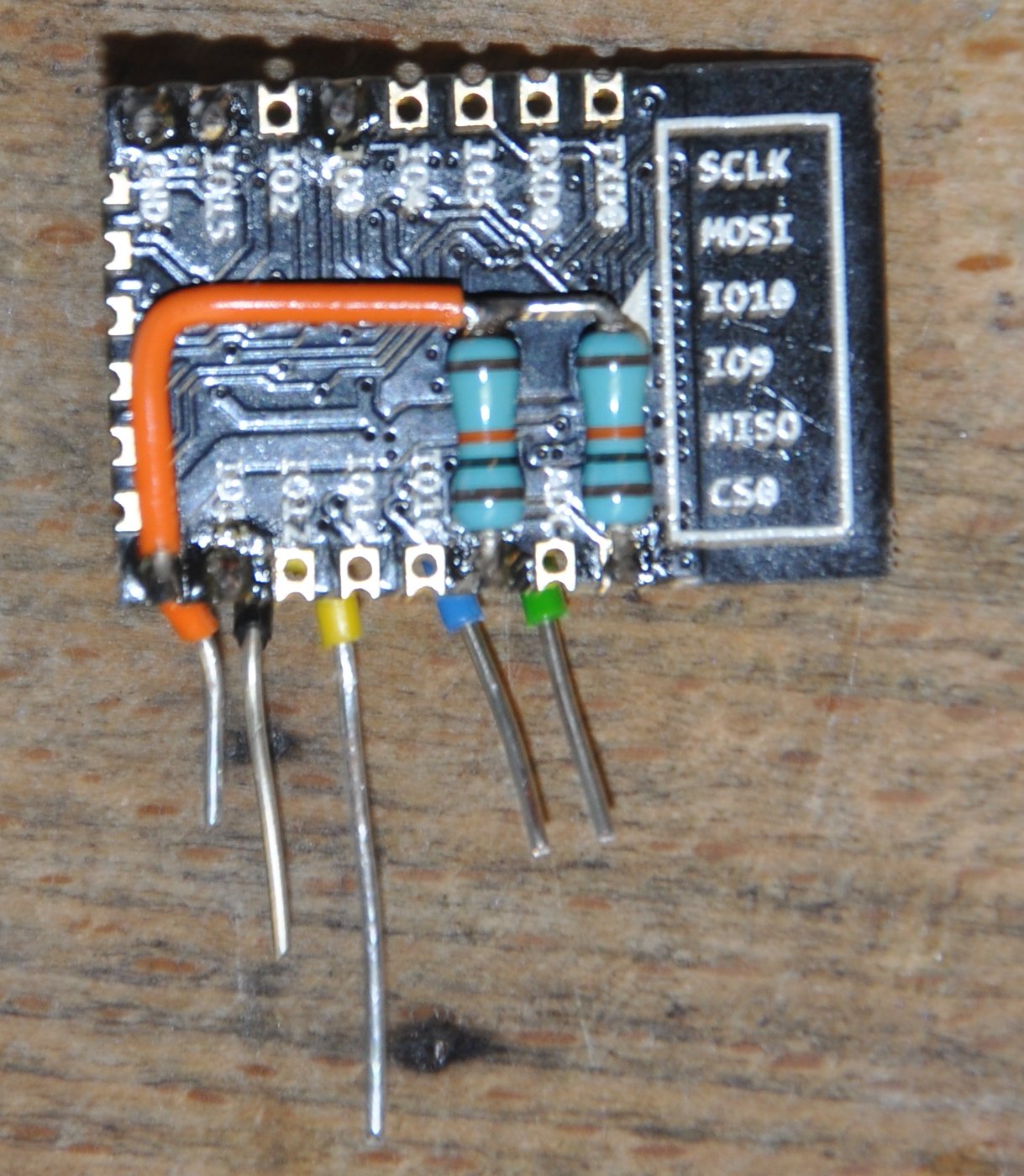
New plan needed: The back of the dead ESP boards were marked with ESP-12-F. Since I need 4 and I'm down to 2 WeMos left I may as well cut out the hassle, South American River Co provided 5 ESP-12F for £13.99 next day. This is the pinout of the ESP-12F from the manual:
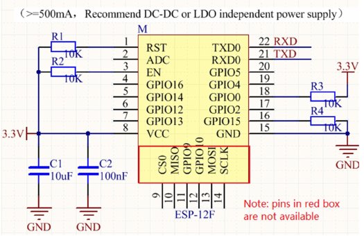
The pinout is not exactly the same as the WeMos carrier above. GPIO15 (yellow wire) isn't a straight connection and EN on the ESP-12F isn't brought out to a pin on the carrier at all. Since that pad was one of the 3 I'd ripped off the 2nd desoldering attempt I had to trace it back (Blue wire).
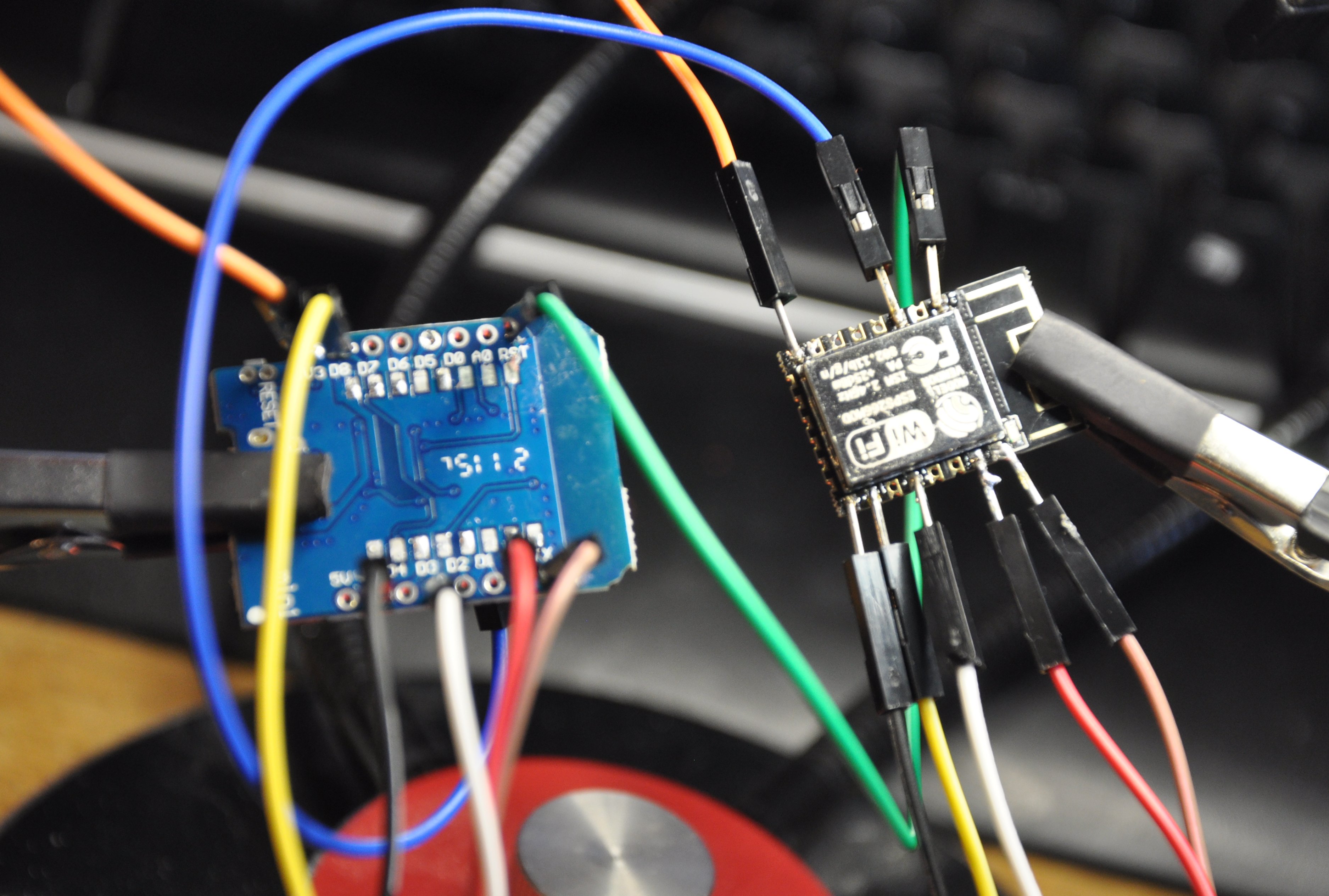
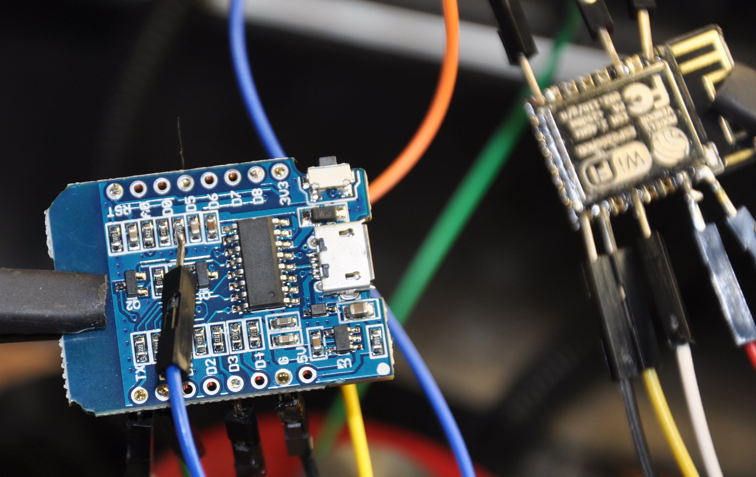
At which point things got really frustrating, it just wouldn't work. I checked and re-checked the documentation and my soldering and still Tasmotizer just wouldn't connect to program the little sod. It turned out to be a combination of 2 problems. Lead free solder (the work of Stan) on the carrier board giving me dry joints, in particular the blue wire to the resistor. How can a mechanically sound joint made entirely of solder not conduct? Grr. 2nd, it took a few resets to get Tasmotizer to connect. With a D1 mini you just plug it in to USB & they wake in programming mode every time. With the wires between the carrier & ESP12F it took a good few resets with Tasmotizer attempting connection to get it to work.
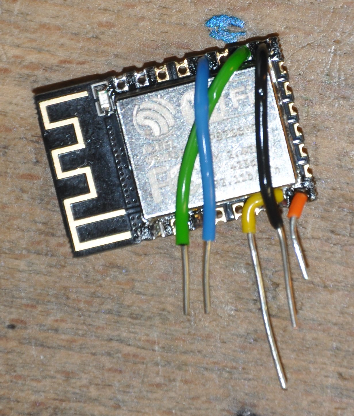
Once programmed I powered the carrier from the bench psu to confirm it was working & desoldered it from the spiders web. Then I could start figuring out how to connect it to the Meross. These are the connections viewed on the underside of the Meross PCB:
     Relay |
            |
HWLBL SELi |
            |
           |
            | LED
  Button 1 |
            | BL0937 CF
       GND |
            | HLWBL CFi
       VCC |
So the 12F needs connecting like this. Connections in brackets are shown for completeness, I don't need them as this PCB doesn't have the power monitoring:
    GPIO15 |
            |
  (GPIO03) |
            |
           |
            | GPIO00
    GPIO13 |
            | (GPIO05)
       GND |
            | (GPIO14)
       VCC |
There's no connection for RST and EN. Those are handled on the riser board, see the 3 little resistors down the bottom (Blitzwolf socket so this is an ESP riser)
So a certain amount of creative bodgery will be required:
And fitted:
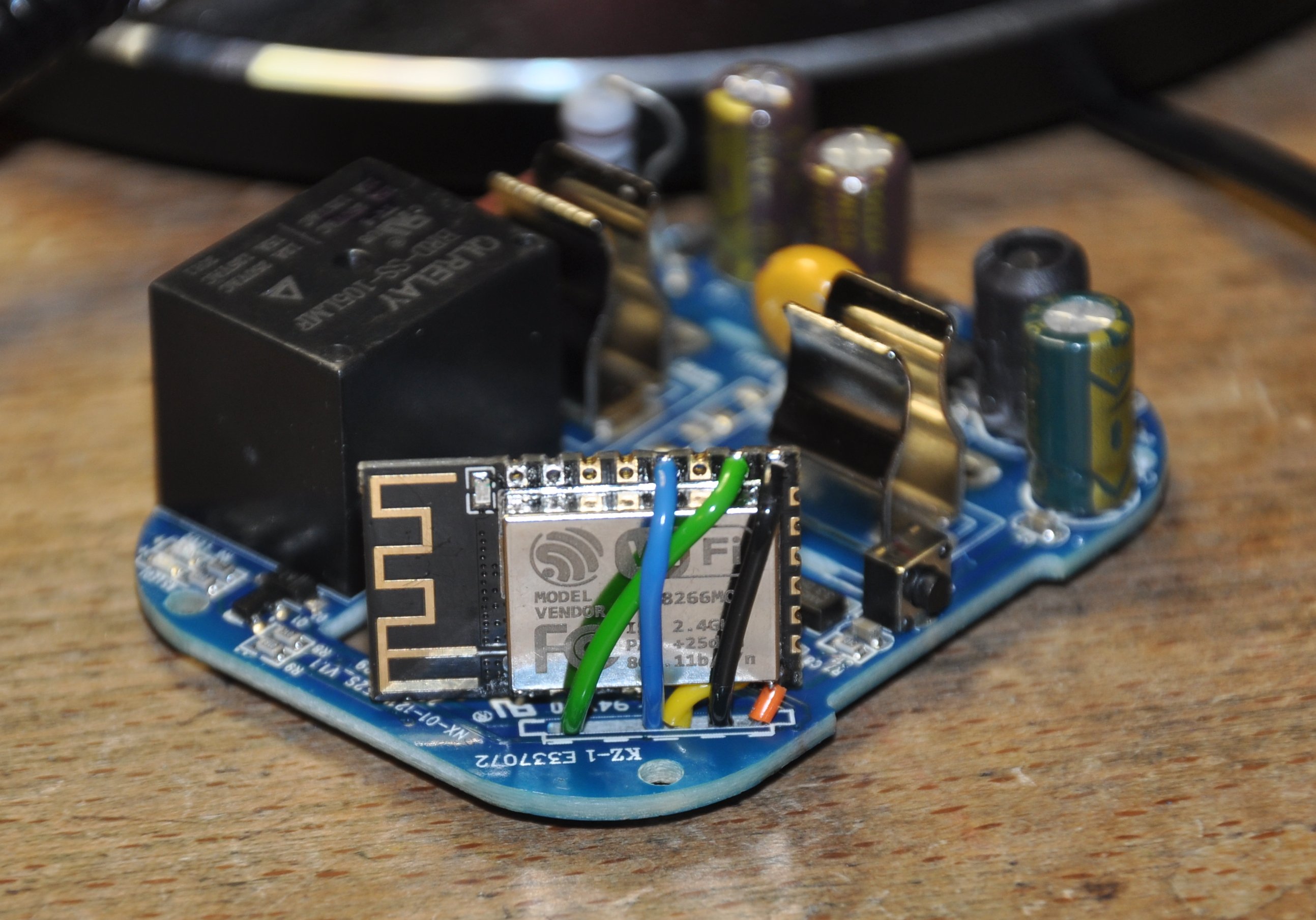
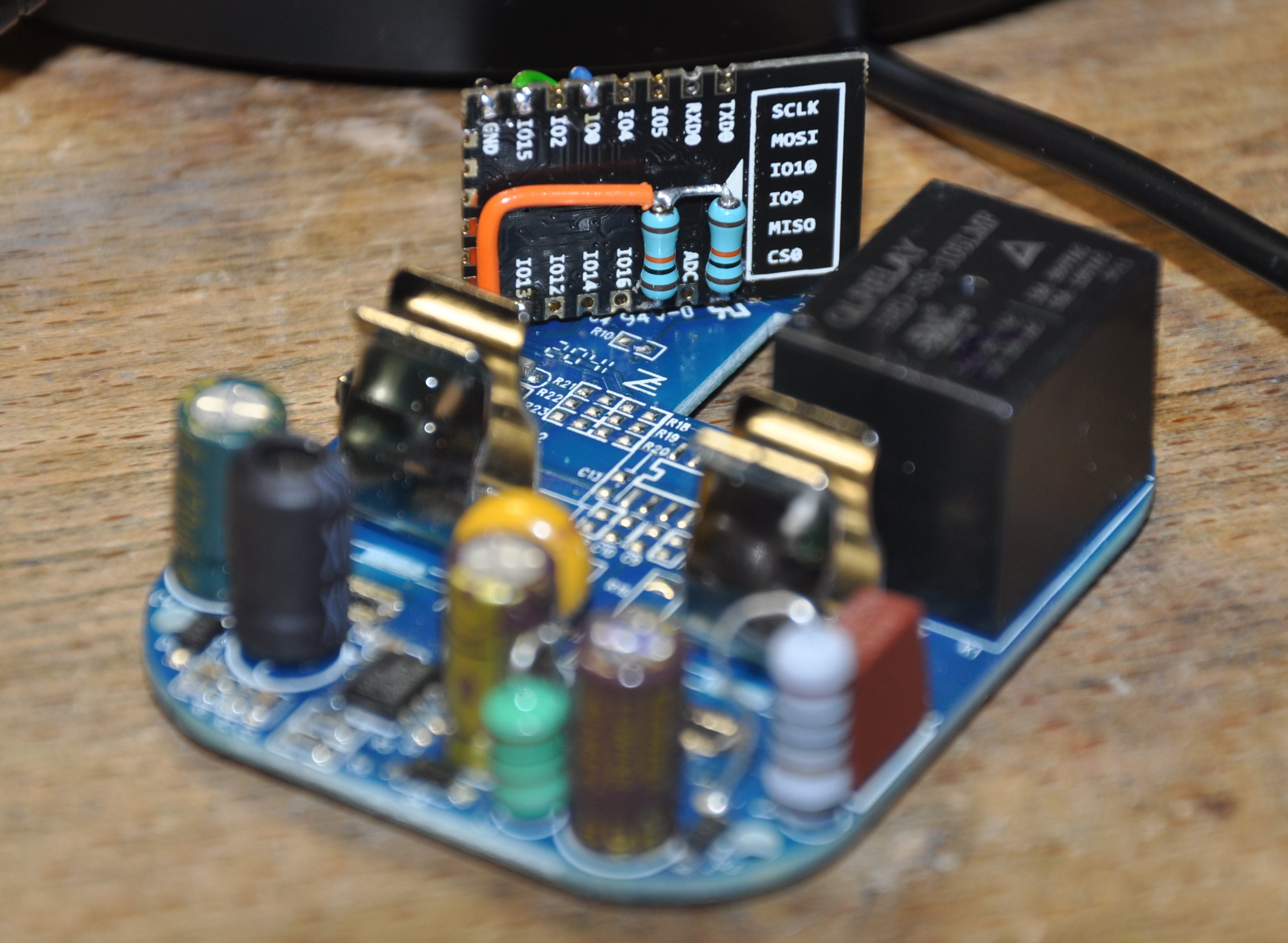
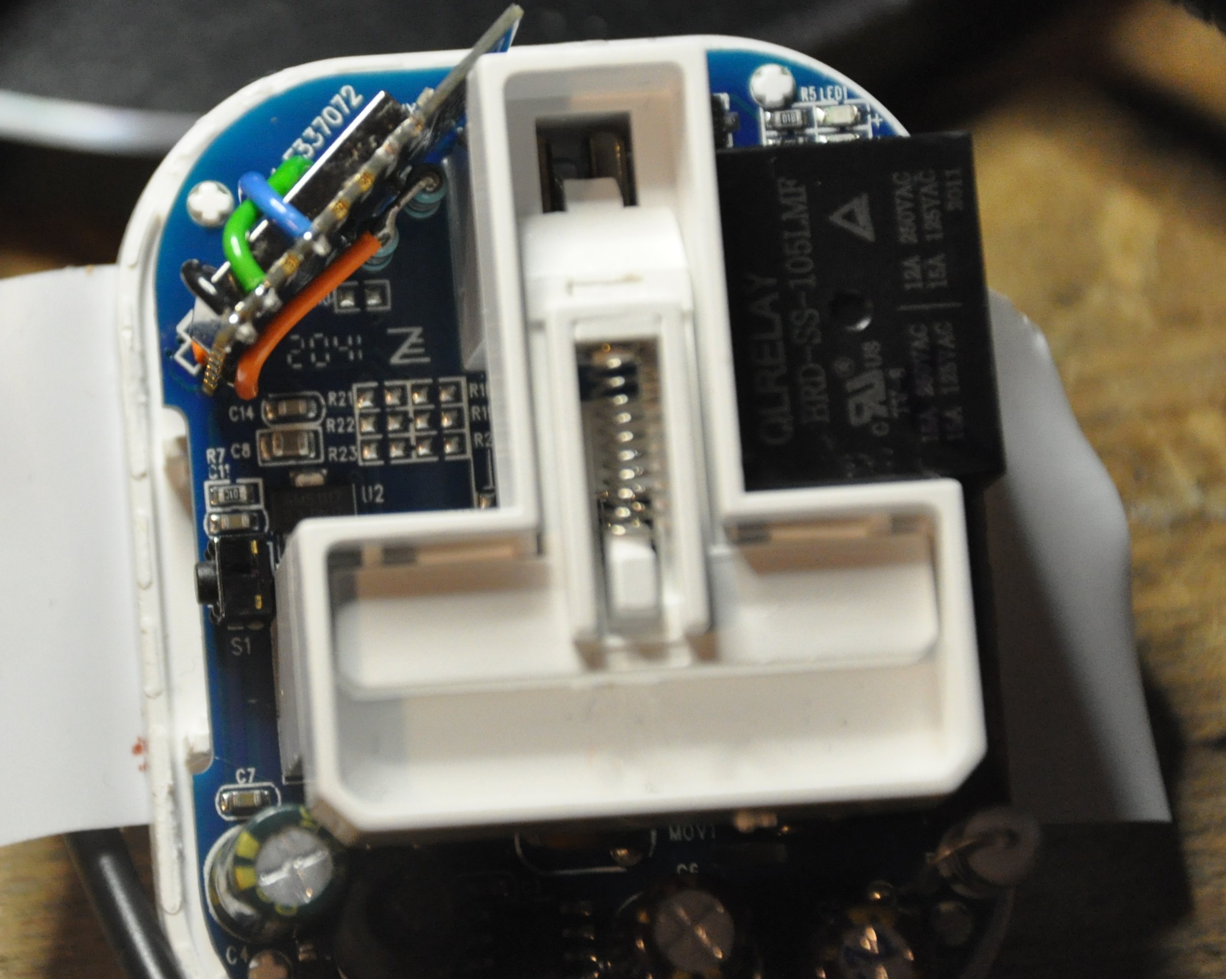
And so remembering to adjust and then double check the voltage I ran it off the bench PSU and lo, it was visible on the network. I blatted Kim's Blitzwolf Template onto it and soldered it back into the socket. And blow me it works

It is of course spouting garbage related to the power monitoring over mqtt but I'll get to that. First I need to just rinse and repeat 3 more times.